|
1951 Chevy Accessories Installation Manual |
||||
|
Insert
drill bushing, furnished, into bracket and tighten clamp screw to grip
drill bushing.
Insert
half inch drill through drill bushing and bracket and drill half inch hole through
corner post as shown in figure
175. IMPORTANT: HOLD DRILL
LEVEL. After piercing the outer
metal of corner post, make
sure that any wires or tubing inside corner post are moved aside before drilling
through the inner metal wall.
Loosen clamping screw and
remove drill bushing from the
bracket and discard bushing.
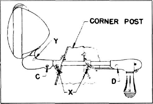
Tighten
the friction screw "C" in figure 176 and remove nut and wedge "D" and remove
handle from light
shaft. |
screw "X"
adjusts the vertical or shaft friction. Friction should be sufficient to hold
lamp in position against wind,
but free enough for easy
operation.
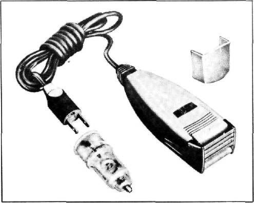
Approximate Flat Rate Time 1 hour. 986418 ELECTRIC SHAVER Procedure
for Installation of Electric Shaver on All Model Passenger Cars and
Trucks. |
|||
 |
||||
 |
||||
|
Figure 177
1. Remove cigarette lighter
element.
2. Plug adapter into cigarette
lighter.
3. Plug cord into other end of adapter and
shave.
4. Remove adapter and replace cigarette
lighter element.
Approximate Flat Rate Time -
NONE
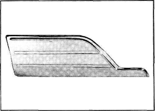
986535 FRONT FENDER SHIELD
Procedure
for Installation of Front Fender Shield on All Model Passenger
Cars. |
||||
|
10. |
Figure 176
Insert the
light through the outside bracket, until the head housing is flush against the
outside bracket. The floating
bushing on light shaft should
go into the recess of outside corner bracket.
Place
inside bracket over light shaft and slide all the way on shaft, with arm up or
down to make best fit against
instrument panel or corner post
as shown in figure 176. The arm
can be bent slightly if necessary. Drill 1/8 inch hole and attach bracket with
self-tapping screw furnished.
See "X" in figure 176. Tighten
bracket clamping screws "C" to
hold light assembly tightly in corner post as shown in Figure 176. Replace handle on light, being sure that the
head housing is pushed flush
against the outside
bracket. Replace wedge "D" and nut. Pass cable under bracket and run down close
to pillar and up under
instrument panel. Clip fuse
holder to instrument panel flange. Connect cable terminal to light switch at
lead from
ammeter.
Head and
Shaft Tension: Set screw "Y" adjusts the horizontal or head friction,
and |
|||
 |
||||
|
Figure 178 |
||||
|
|
||||
|
73 |
||||
|
|
||||
| « PREVIOUS PAGE | CONTENTS PAGE | NEXT PAGE » |
|
|