|
1951 Chevy Accessories Installation Manual |
|||
 |
|||
|
|
|||
|
Figure 94 |
|||
|
|
|||
|
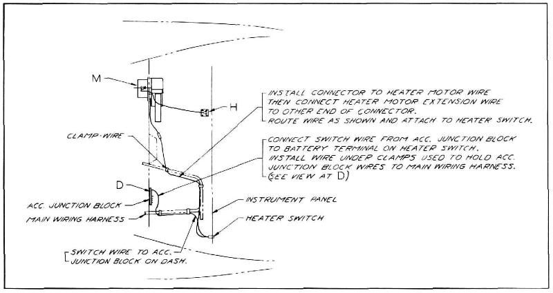
and shut off valve, (see "A" in
figure 91).
12.
Install water hose, clamps and bracket as shown, making sure that the upper hose at
"B" on engine is connected to
the lower pipe at heater, (see
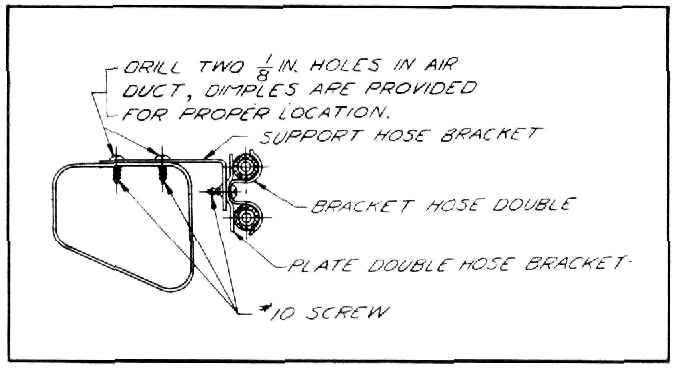
figure 91). Dimples in air duct
are provided to locate position for drilling bracket holes, (see figure
95). |
986104 AIR FLOW HEATER |
||
|
Procedure
for Installation of Air Flow Heater
on All
Model Trucks.
(Special
Instructions for Cab Over Engine Models) |
|||
|
|
|||
 |
 |
||
|
Figure 95
13. Install stop as shown in view "M" by
removing screw, place stop
in position then replace
screw, (see figure 90).
14. Refill radiator while engine is running to
eliminate trapping air in
heater system.
15. Make sure that operating instruction tag is
furnished to the
customer. |
|||
|
Figure 96
1. Remove cover plate from right-hand inside
cowl panel. Remove round cover plate from the right-hand side of the front of dash
and cut hole in dash mat to
match, (see figure 97).
2. Cut two holes in dash mat for water
hose |
|||
|
Approximate Flat Rate Time 1.3
hours. |
|||
|
|
|||
|
36 |
|||
|
|
|||
| « PREVIOUS PAGE | CONTENTS PAGE | NEXT PAGE » |
|
|