|
1951 Chevy Accessories Installation Manual |
|||
 |
|||
|
|
|||
|
Figure 80 |
|||
|
|
|||
|
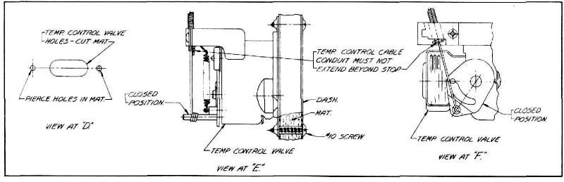
5. Temperature control valve; on right hand
side of dash, cut holes in
dash mat through punched holes
provided in dash. See view at
"D." Attach medium length control cable to valve and tighten clamp screw securely,
cable conduit to be against
the stop provided. Install
valve as shown using screws. See views at "E"or "F" for optional valves,
(see figure
81).
6. Reinstall Glove
Compartment.
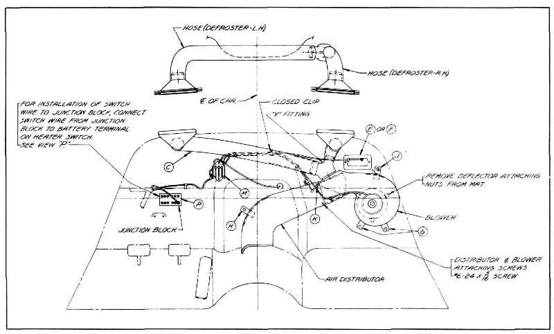
7. Blower and Distributor; attach air
distributor to blower with
three #6 sheet metal screws as
shown in figure 81. Make sure defroster valve operates freely. Punch
holes in dash mat for mounting
bolts, en- |
larging
the one at "H" to take the spacer. Slide entire assembly into place and attach
as shown in figure 80. The
upper mounting bracket on
the blower is secured to dash with a sheet metal screw inserted from the
engine side as shown in view at
"J" while the two lower
mounting brackets on the blower and the one on the distributor are
secured to dash with bolts
inserted from passenger side. See views at "G" and "H." Attach "Y" fitting to defroster outlet on
top of distributor. (See figure
82.) Controls: Assemble large
rubber grommet in dash and
small rubber grommet in dash leg as shown in figure 79. Cut a
suf- |
||
|
|
|||
 |
|||
|
|
|||
|
Figure 81 |
|||
|
|
|||
|
31 |
|||
|
|
|||
| « PREVIOUS PAGE | CONTENTS PAGE | NEXT PAGE » |
|
|