|
1951 Chevy Accessories Installation Manual |
|||
|
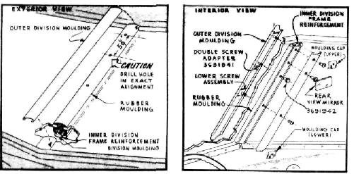
5. Remove rear view mirror upper and lower
inner division moulding caps.
Loosen top and bottom cross
slotted barrel nuts to remove the inner and outer division mouldings
as shown in figure
208.
6. Pierce tab of blind hole in rubber moulding
(approximately 5-1/4 inches
below top hole), using this
hole to guide the spot drilling of a 9/32 inch hole through the inner division
frame reinforcement.
NOTE:
Carefully align the drilling through the rubber moulding to maintain the 5-1/4
inch center dimension of holes
for the adapter assembly,
as shown in figure 208. |
 |
||
|
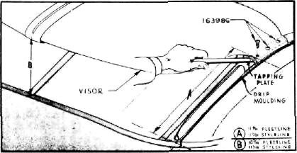
Figure 209
pencil
marks on right drip moulding. Make sure the top edge of tapping plate is flush
with top edge of drip moulding. Scribe the three holes, center punch and drill holes
with a number 21
drill.
CAUTION: Drill through drip
moulding only. Repeat this operation
for left side.
10. Clean out drip mouldings. Place tapping
plate marked "L" inside of left
moulding and tapping plate
marked "R" into right moulding, align with holes that were
drilled in drip mouldings. To
facilitate use of self-tapping
screws during installation, we recommend that each screw be run
through the holes in both
tapping plates before mounting the visor as shown in figure
209.
11. Place visor in position, realign all holes,
insert and firmly fasten all
six tapping screws as in figure
209.
12. Insert knife edges of center clamps between
outer division moulding and
rubber. CAUTION: Do not touch
glass with center clamps.
Firmly fasten clamping screws and nuts. Adjust center support to assure full
curvature of visor and firmly
fasten adjusting clamp and
nuts.
Approximate Flat Rate
Time .9 of an hour. 986544 RIGHT-HAND SUN
VISOR
Procedure
for Installation of Sun Visor on All
Model Passenger Cars. |
|||
 |
|||
|
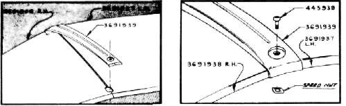
Figure 207
7.
Discard upper individual screw assembly, slip double screw adapter and
remaining lower screw assembly into
the outer moulding, insert
the three threaded studs through rubber (with adapter to the top), firmly
fasten the brass barrel nut to middle stud. Hold inner moulding in
place and firmly fasten the two
remaining cross slotted barrel nuts. Replace upper and lower moulding caps and
rear view mirror as shown in
figure 208. |
|||
 |
|||
|
Figure 208
8. Position visor on car as shown in figure
209 using "A" dimension as average height on drip moulding. "A"
dimension is recommended for
average Installations but can be varied to suit the driver by moving visor forward
or backward on drip moulding (hold "A" dimension equal on both sides). When
position has been
determined pencil mark "A" dimension on drip moulding as shown in
figure
209.
9. Align lower edge of right tapping plate,
with |
|||
 |
|||
|
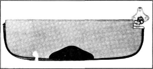
Figure 210 |
|||
|
|
|||
|
87 |
|||
|
|
|||
| « PREVIOUS PAGE | CONTENTS PAGE | NEXT PAGE » |
|
|